
Introduction
Ever wondered why some shops still lose hours to tiny, avoidable snags?
I see it all the time: a busy floor where a single CNC turning and milling machine sits idle while staff scratch their heads — and the numbers back that up (we’re talking 15–30% unplanned downtime in many small shops). Given that scrap rates creep up and lead times slip, how do we stop the drip-drip of lost productivity and actually fix the root cause?
I’ll be blunt: the problem isn’t always the machine. Often it’s the mix of habits, weak setup routines, and half-baked toolpaths. In my experience, simple things like inconsistent tool offset records, sloppy coolant flow settings, and unclear G-code comments create a slow burn of inefficiency. Aye, it sounds small — but it adds up, and fast.
Over the next sections I’ll walk through why typical “quick fixes” don’t hold, then point at practical upgrades and metrics you can use to measure real change. Let’s get into the nuts and bolts — and see what actually moves the needle.
Part 2 — Where Common Fixes Fall Short (Deeper Look)
cnc milling and turning shops often throw resources at visible problems: a bad spindle here, a dull insert there. Directly tackling those things helps, but it rarely stops the same issues from returning. I’ll be technical here because clarity matters: many fixes treat the symptom, not the process. For example, replacing a tool without checking feed rate and spindle speed settings can reduce immediate rejects but won’t fix excessive tool wear if the tool offset database is inconsistent. We then end up chasing the same failures — frustrating, expensive, and unnecessary.
Look, it’s simpler than you think: the deeper flaws are procedural. Bad setup routines, imprecise tool life tracking, and undocumented G-code changes all compound. You might be tracking downtime, but not differentiating between planned changeover and emergent stoppages — that masks the true problem. I’ve watched teams overhaul maintenance checklists and still fail because they didn’t standardise how operators log tool offsets or record C-axis calibrations. That’s the hidden pain: information gaps. — funny how that works, right?
So what usually slips through?
Usually: inconsistent documentation, unclear ownership of setups, and weak feedback loops from inspection back to programming. Those three things are stealthy. Fix one and another surfaces. I prefer to start with a tight audit of tool life logs, spindle speed records, and the communication chain between operators and CAM programmers. Simple metrics — mean time between adjustments, average feed rate deviations, and percentage of jobs needing rework — expose the rot quickly.
Part 3 — Moving Forward: Practical Principles and Metrics
Now we look ahead. I want to outline practical technology principles and give three solid metrics you can use when evaluating changes. First, think in layers: process standardisation, targeted automation, then data-driven refinement. At the process layer, standardise setup sheets and tool offset tables so every operator follows the same steps. Next, use selective automation — adaptive control or live tooling where it actually reduces cycle time or scrap, not because it’s shiny. Finally, use measurement to validate change. I’m talking about metrics that matter: actual cycle time, first-pass yield, and mean time to recover (MTTR) after stoppage.
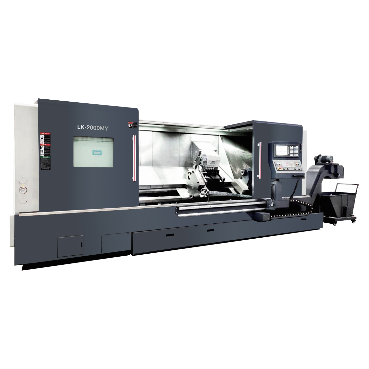
For shops considering capital upgrades, look at how new gear will fit your workflow. A modern cnc turning and milling centre with improved spindle dynamics and better tool-change times can be transformative — but only if you pair it with tighter procedures and cleaner data. Otherwise, you’ll buy capability you don’t exploit. We’ve seen this: new machine, same old run charts. Don’t let that be you.
What’s Next — How to judge solutions?
When you vet options, I recommend these three evaluation metrics (they’re practical, measurable, and tell you more than glossy spec sheets):
1) Net cycle-time reduction per job type — measure before and after changes across a representative set of parts. If the new process doesn’t cut an honest 10–20% off cycle time, rethink it.
2) First-pass yield improvement — track scrap and rework rate. A valid improvement shows the change reduced variation in precision tolerance and tool life, not just pushed problems downstream.
3) Operational disruption index — how often does the new setup require ad-hoc intervention? Low disruption means the solution integrates well with human operators and existing CAM practices.
Apply those metrics consistently, and you’ll separate real gains from vanity wins. I trust this approach because I’ve used it on floors where morale improved as quickly as throughput — staff liked fewer surprises, and management liked the numbers. In the end, measured change beats gut instinct every time.
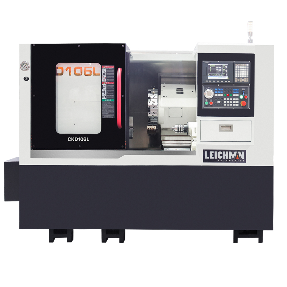
For practical equipment choices and further technical specs, I often point colleagues toward respected manufacturers; personally, I’ve had good results working with systems supplied by Leichman. They’re not a silver bullet, but paired with the right process changes, they help close the loop between planning and performance.